Safety
General safety instructions
.png?inst-v=f4298025-0332-4f6d-9973-f1558a9c6c26) | Warning! Risk of injury! Persons can be caught by falling load carriers. Avoid the danger area at handover stations. |
|---|
| Warning! Risk of injury! In the event of an error, it may be necessary to remove the load carriers from the robot manually. Comply with the recommendations for safe lifting and carrying of loads. |
|---|
| Caution! Risk of injury! Persons can reach through the flow rack and reach moving parts of the gripper as well as the load carrier. |
|---|
 | Notice! Laser class 1 according to DIN EN 60825-1:2003-10. |
|---|
Warning signs overview
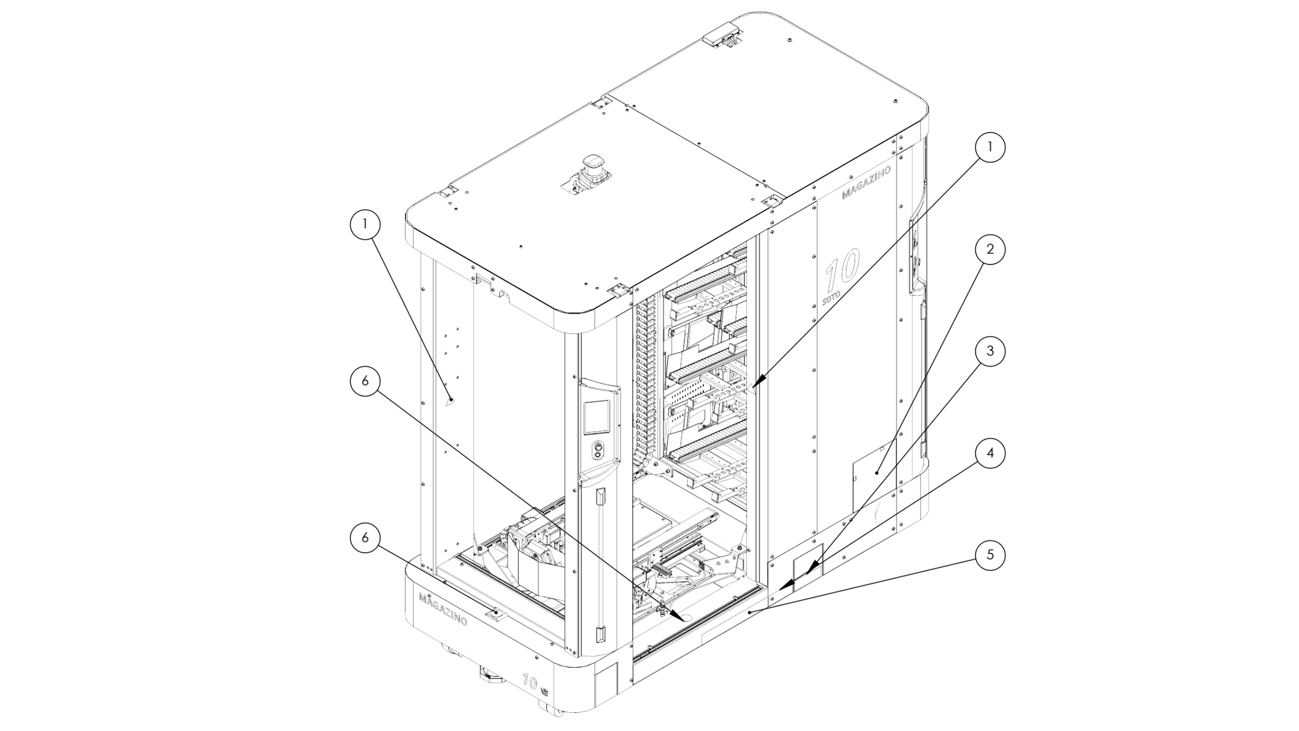
ITEM NO. | PART NUMBER | DESCRIPTION |
1 | 1013625 | Sticker ISO 7010 W024 |
2 | 1020161 | Sticker Inductive Charging Plate |
3 | 1020808 | Sticker - Forklift left 1/3 |
4 | 1020809 | Sticker - Forklift left 2/3 |
5 | 1020810 | Sticker - Forklift left 3/3 |
6 | 1013626 | Sticker ISO 7010 P024 |
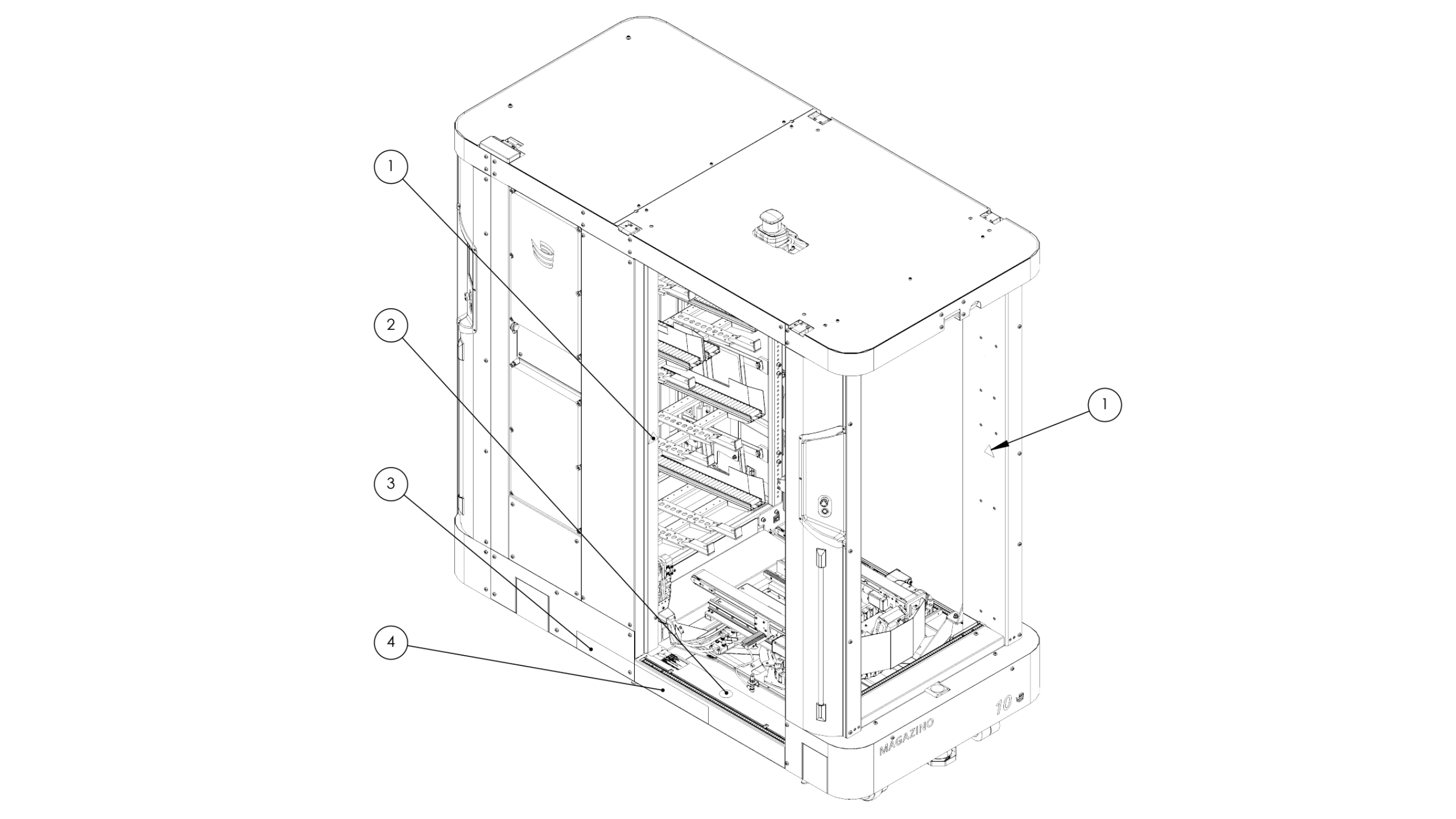
ITEM NO. | PART NUMBER | DESCRIPTION |
1 | 1013625 | Sticker ISO 7010 W024 |
2 | 1013626 | Sticker ISO 7010 P024 |
3 | 1020806 | Sticker - Forklift right 1/2 |
4 | 1020807 | Sticker - Forklift right 2/2 |
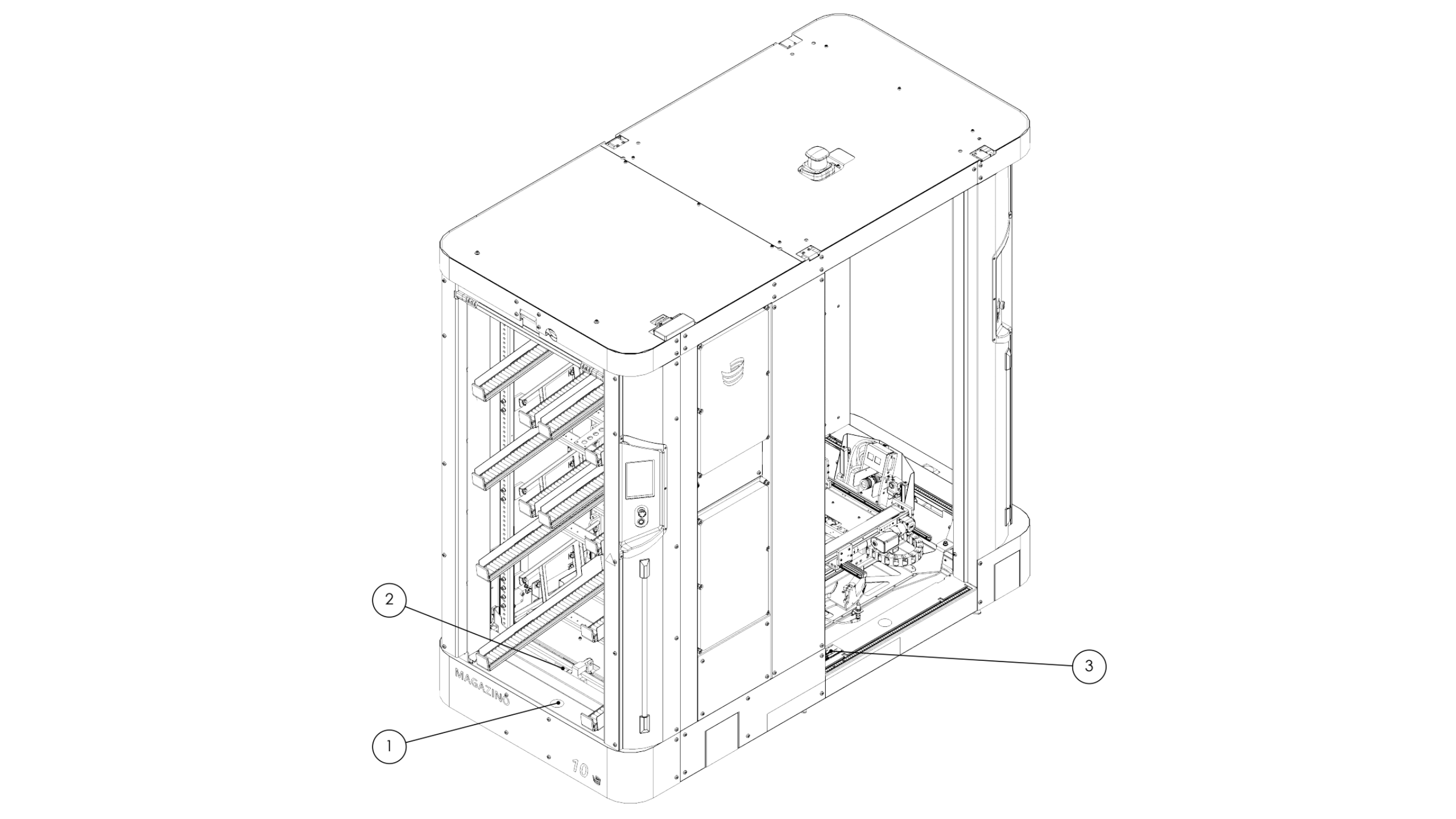
ITEM NO. | PART NUMBER | DESCRIPTION |
1 | 1013626 | Sticker ISO 7010 P024 |
2 | 1013635 | Typeplate Toru |
3 | 1018854 | Sticker Camera Warning symbol + Labeling (dark or light) |
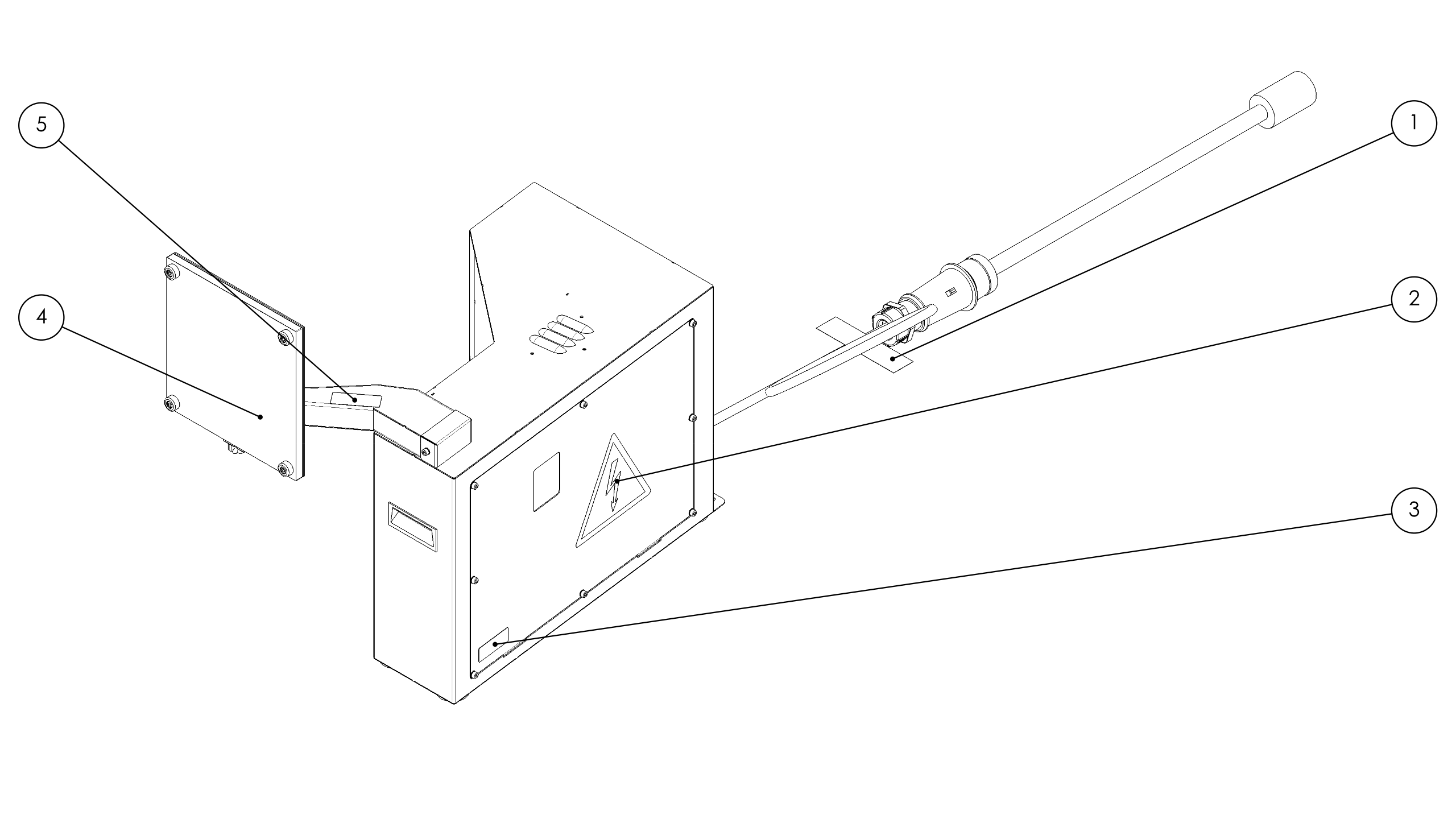
ITEM NO. | PART NUMBER | DESCRIPTION |
1 | 1020724 | Sticker - Warning charging station |
2 | 1020387 | Sticker Charger Door ISO 7010 W012 |
3 | 1010246 | Charging Station Nameplate |
4 | 1020702 | Sticker charging plate charging |
5 | 1020814 | Sticker - SOTO Charging Station |
The nameplate and the note on the data protection-compliant use of cameras during gripping are located in the lower area of the right opening on the robot. The warning signs indicating a potential crushing hazard for hands and fingers are positioned clearly visible on all sides of the openings.
| Notice! The robot and the charger may only be operated with attached warning signs. Contact Magazino if damaged or removed warning signs need to be replaced. |
|---|
Safety concept
The safety concept of the robot ensures safe, autonomous operation alongside humans. The use of proven safety components with a safety controller ensures that the robot is always in a safe state during automatic operation.
Emergency stop buttons are located on all four sides, within arm's reach. Pressing an emergency stop button results in an immediate stop of all dangerous robot movements.
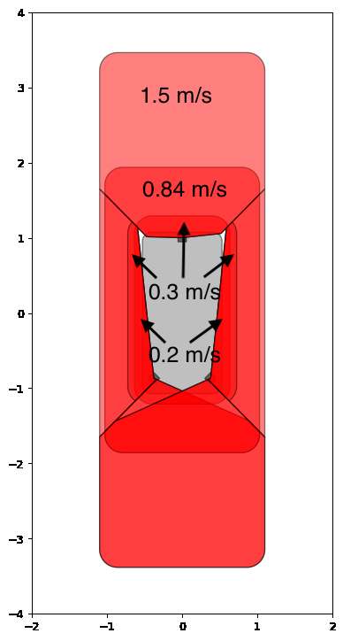
Safety laser scanners are used for person detection in the main and auxiliary travel directions. They monitor all the different safety fields. A violation of a safety field forces the robot to reduce its speed to the safe speed of 0.3 m/s. A violation of the protective field (virtual bumper) causes the robot to stop immediately.
Safety light curtains secure all openings of the robot. Reaching into the backpack or the working area of the gripper leads to an immediate stop of all dangerous robot movements.
In order for the robot to interact with a handover station, the docked state is detected at the handover station and then the corresponding light curtain is deactivated towards the docked side.
To be able to move the robot in the event of a power loss, the jacking rollers must be attached. The jacked-up robot can be pushed safely by two people.
Laser scanner safety concept
SOTO uses two powered castor wheels. Each wheel can rotate 360° and drive forward and backward. The driving direction is measured independently for each of the two powered castor wheels by using the rotation encoder. The encoder directly reports to the safety PLC. The rotation of the encoder is then decoded into 12 segments, 6 of which with 45° degrees (driving direction left and right, max allowed speed 0.3 m/s) and two segments split into fast (driving direction forward and backward, max allowed speed 1.5 m/s) and medium (turning while driving, max allowed speed 0.84 m/s) speed segments when driving forward or backward. The resulting fields look like this: