
TORU 5.5 Components
General overview
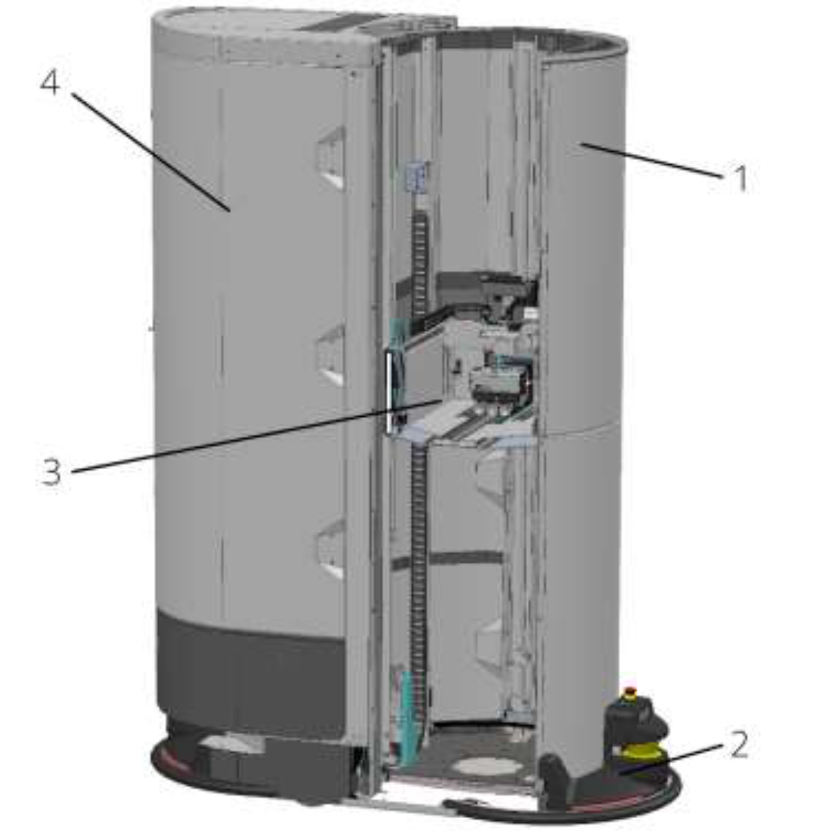
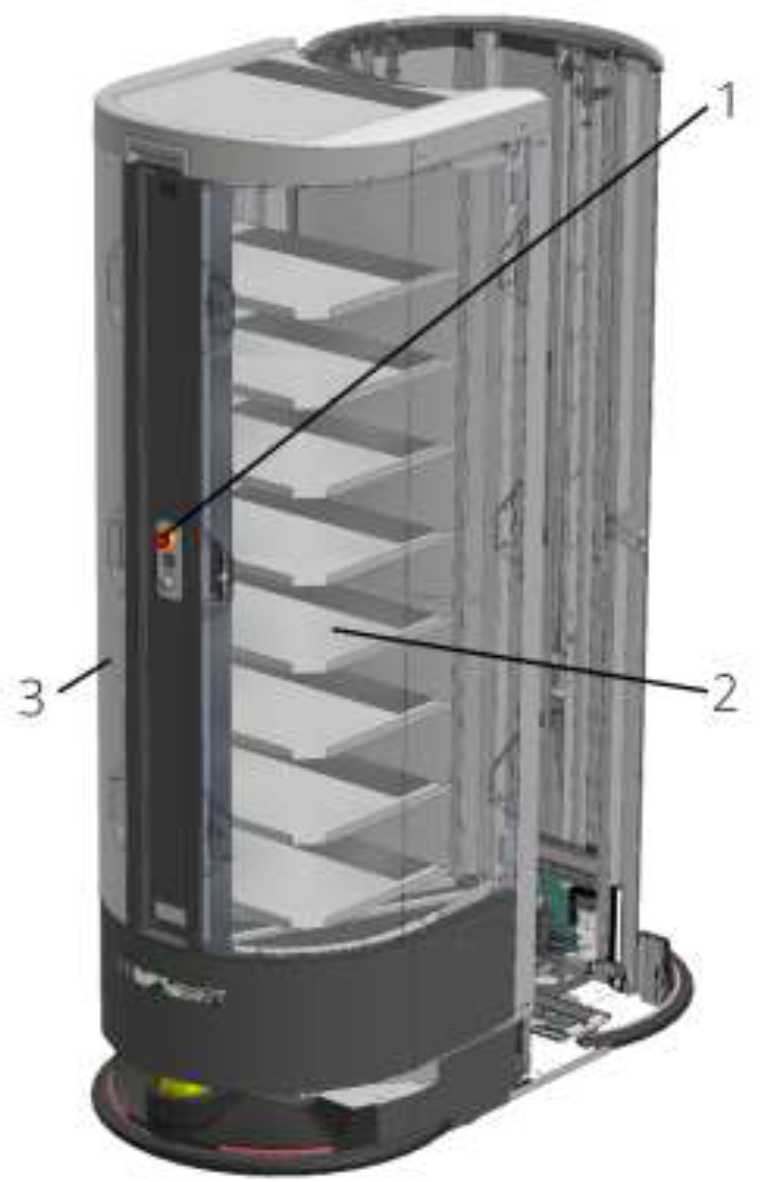
1) Tower, 2) Drive unit, 3) Shoebox handler, 4) Backpack
TORU 5.5 essentially consists of four components. The Shoebox Handler (3) is used to handle the objects to be picked. The tower (1) protects people from dangerous machine movements. The Drive Base (2) establishes contact with the floor. The Backpack (4) serves as storage for the objects to be picked.
Shoebox handler
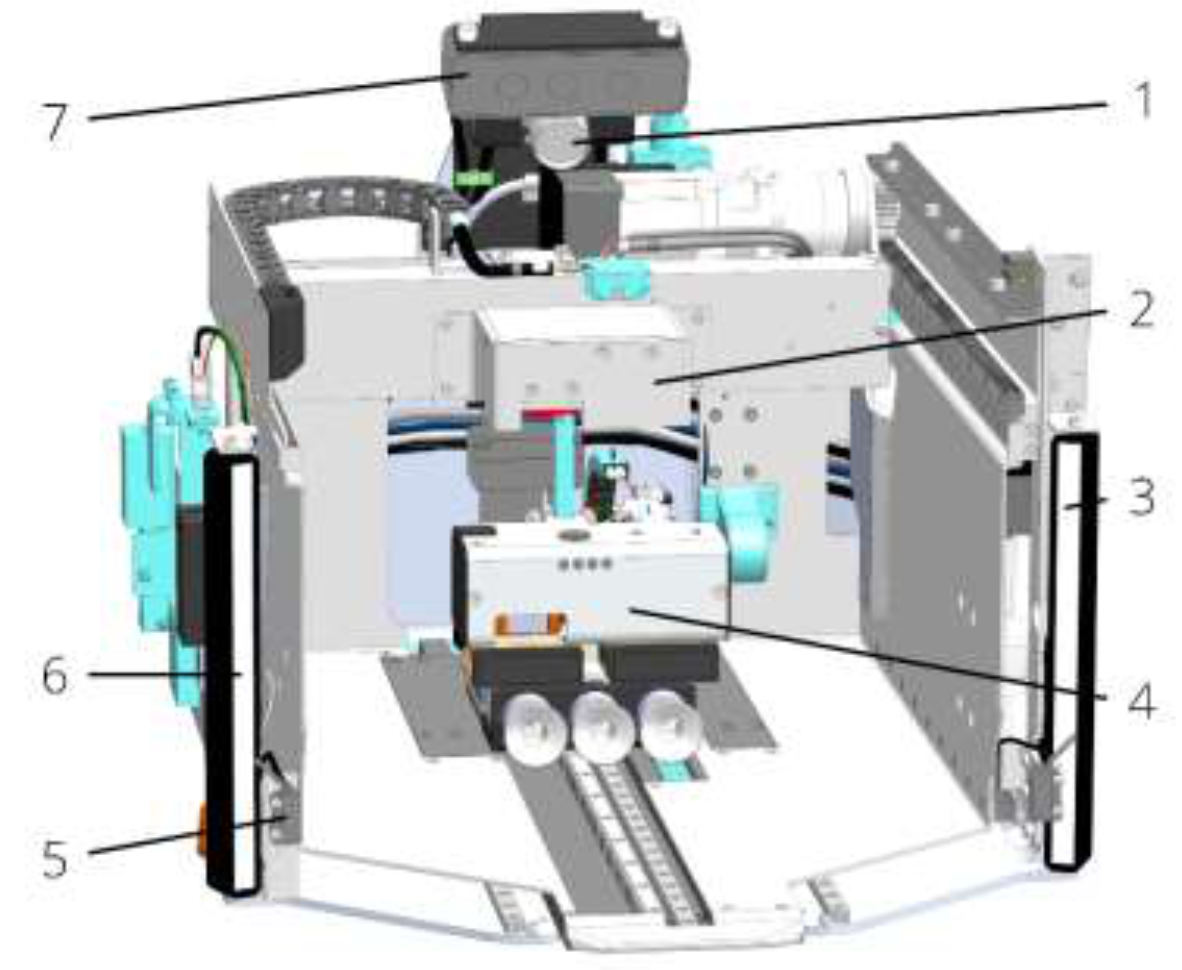
1) Barcode camera, 2) Pushback unit, 3) LED left, 4) Vacuum unit, 5) Light barrier, 6) LED right, 7) 3D camera
The shoebox handler interacts with the objects to be picked. The 3D camera enables the gripper to recognize the position, size, and orientation of the objects in the picking rack. The barcode camera is used to recognize barcodes on the shoebox. Thanks to the pushback unit, the shoeboxes can be pushed back into the picking rack above the lowest box when a stack of boxes has been gripped.
Front cover
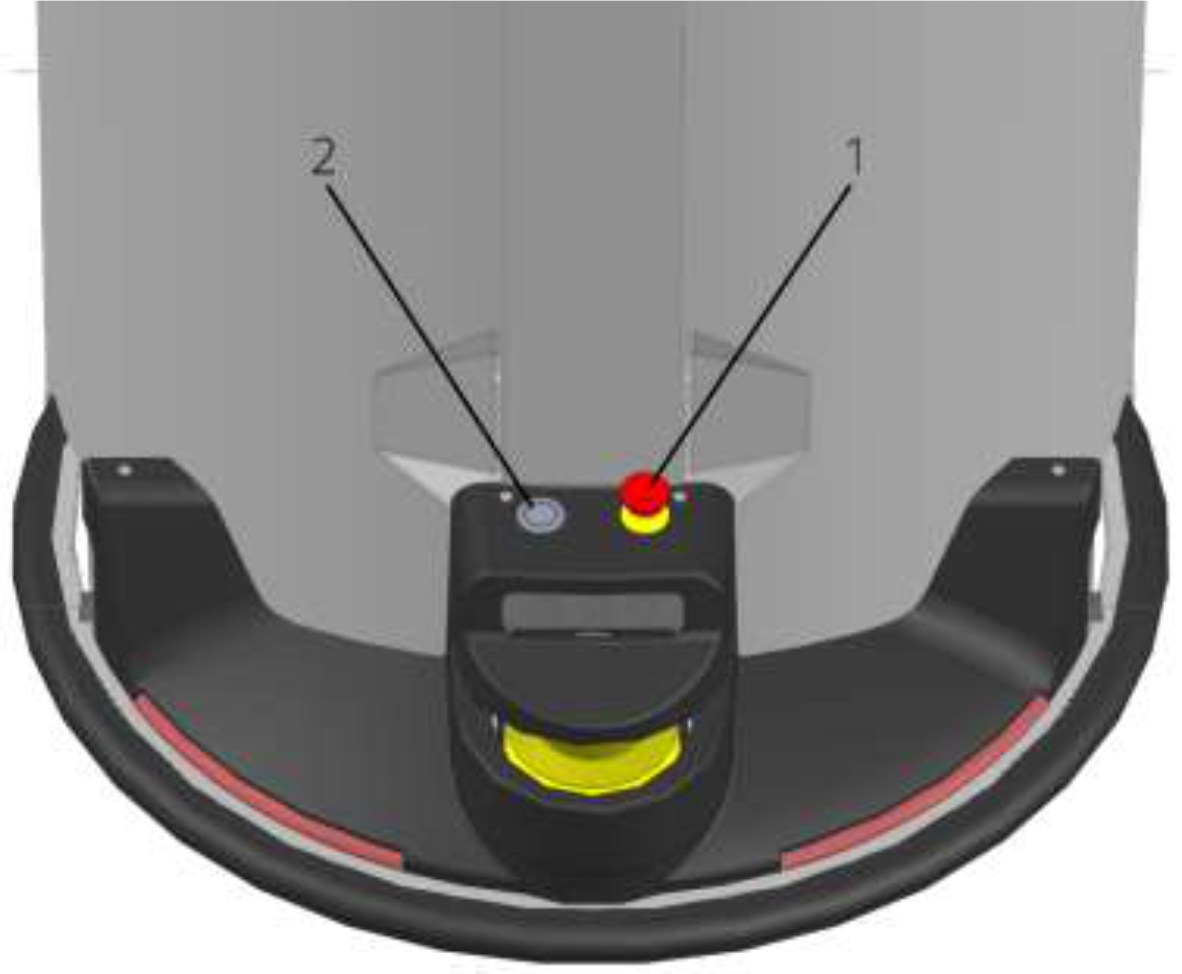
1) Emergency stop button, 2) Push button
The front cover protects the inside of the robot. An emergency stop button (1) and a pushbutton (2) are mounted on it.
Tower
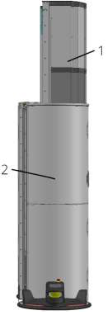
1) Tower inside, 2) Tower outside
The Tower consists of two parts, the inner Tower (1) and the outer Tower (2). The outer Tower protects people from reaching moving machine parts. The inner column extends with the gripper when the Tower is telescoped. The Tower can be rotated and opens only in the direction of the rack.
Backpack
1) Control panel, 2) Backpack door, 3) Right side panel
The backpack serves as storage for the gripped boxes. The control panel (1) is located in the center of the backpack. The backpack door and the cover (2, 3) protect people from reaching moving machine parts. They are screwed and can be dismantled for maintenance work and process observation.
Control panel
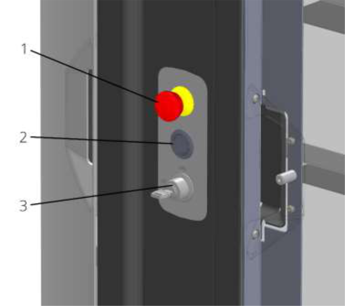
1) Emergency stop button, 2) Push button, 3) Key switch
The control panel consists of three elements. When pressed, the emergency stop button (1) stops all dangerous movements of the robot. The pushbutton (2) is used to return the robot to normal operation after an emergency stop. The key switch (3) can be used to switch the robot can be switched on and off.
Drive base
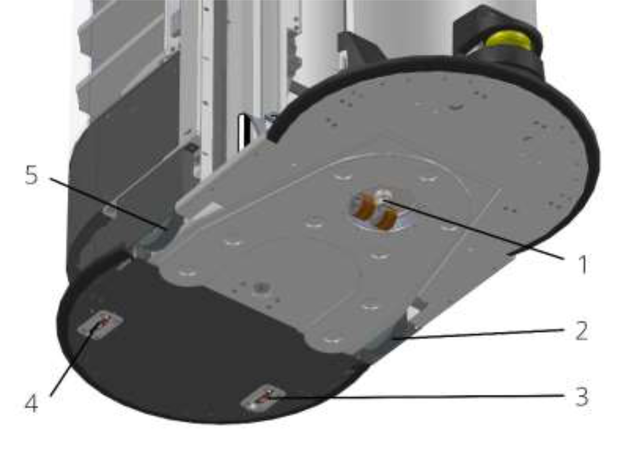
1) Castor wheel, 2) Drive wheel left, 3) Loading contact left, 4) Charging contact right, 5) Drive wheel right
.png?inst-v=f4298025-0332-4f6d-9973-f1558a9c6c26)
| Caution! Laser class 1 according to DIN EN 60825-1:2003-10. All sensors used have at most laser class 1. |
|---|
The drive base makes contact with the ground. It is equipped with safety devices and sensors to sense the environment around the robot. The industrial PC controls the robot, while the safety control prevents dangerous movements of the robot.
Charging station
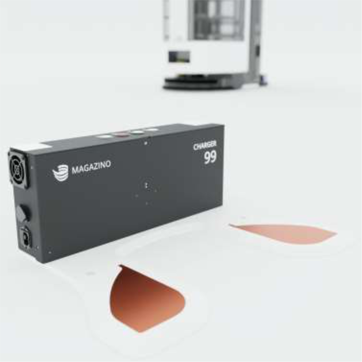
The charging station is used to charge the batteries of the robot. The charging station is approached automatically by the robot during normal operation. A deactivated robot can be pushed manually to the charging station (see “Charging the robot manually”).
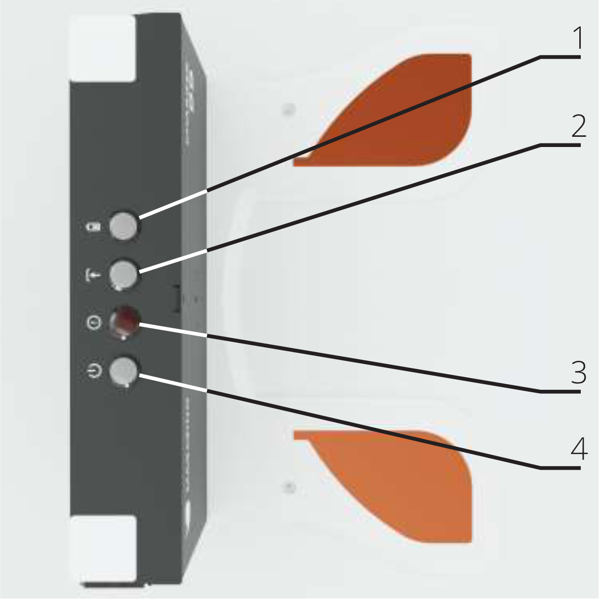
1) Charging state, 2) Docking state, 3) Error detection, 4) Power supply state.
The charging station has four LEDs above the charging station. The individual LEDs and the interaction of several LEDs provide feedback on the current status of the charging station and the charging process.
Troubleshooting the charging station

| Meaning |

| The charging station is off.
|

| The charging station starts up.
|

| The charging station has detected an error.
|

| A robot has been detected, but is not yet in the loading position. Change the position of the robot until the loading position has been detected. |

| The robot is charging. |

| The robot is fully charged. |
Pictogram | Meaning | Pictogram | Meaning | ||
|---|---|---|---|---|---|

|
| The LED does not light up. | 
|
| LED flashes |

|
| LED lights up. | 
|
| LED flashes |
Mounting the charging station
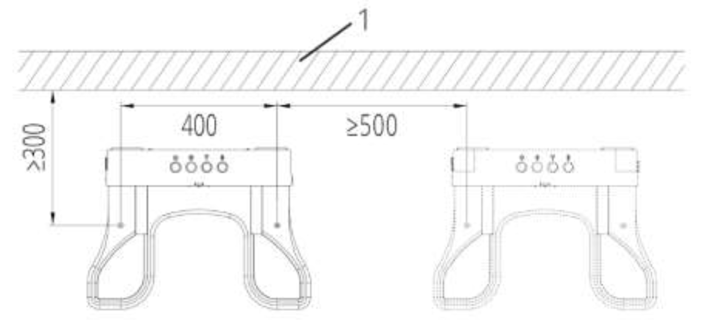
1) Wall
The charging stations must be firmly screwed to the floor. The holes for mounting must be prepared as shown above.
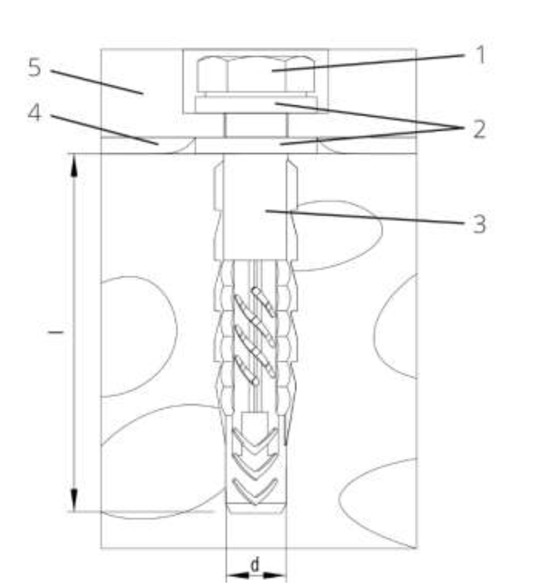
1) Hexagon head screw (d = 6 mm, l ≥ 30 mm), 2) Washer, 3) Dowel, 4) Foam rubber mat, 5) Base plate of charging station